
How to use a Breadboard
A breadboard lets you build and test an electronic circuit without soldering anything permanently. Components and jumper wires are pushed into the holes, held in place by metal clips underneath the plastic surface.
That makes a breadboard ideal for learning. You can build a circuit, test it, move a wire, replace a component, and try again without damaging the parts.
The holes may look like one large grid, but they are not all connected together. Learning which holes share an electrical connection is the most important part of using a breadboard.
What Is a Breadboard?
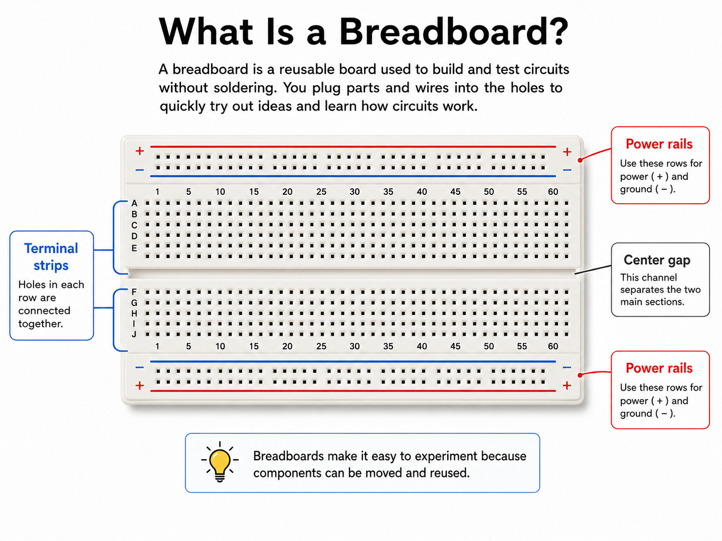
A standard breadboard has three main areas:
The long power rails near the top and bottom
The two large terminal-strip sections in the middle
The center gap separating those middle sections
The power rails are normally used to distribute power across the board. The middle sections hold components such as resistors, LEDs, buttons, sensors, and integrated circuits.
The breadboard itself does not provide power. It simply creates temporary electrical connections between components. You still need a battery, power supply, microcontroller, or another safe low-voltage power source.
How the Power Rails Work
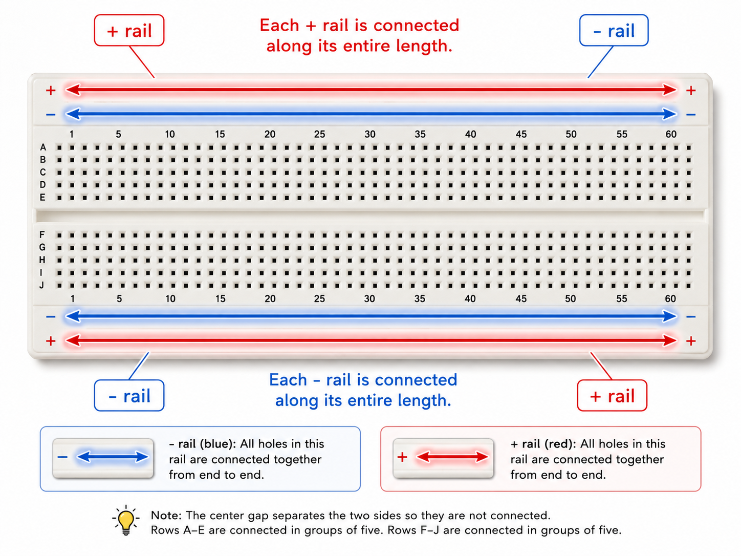
The long rows marked with red and blue lines are called power rails.
By convention:
Red is usually used for the positive supply
Blue is usually used for the negative connection or ground
These colours are only labels. A breadboard does not know which rail is positive or negative. The rail becomes positive only after you connect it to the positive terminal of your power source.
In a simple battery circuit, the blue rail is often connected to the battery’s negative terminal. This is sometimes called ground, although “negative return” is a more accurate description for many beginner circuits.
The holes along one rail are connected together underneath the board. If you connect a battery’s positive wire to one hole in the red rail, you can access that positive voltage from other holes along the same rail.
However, there are a few important details:
The red and blue rails are separate from each other. The upper rails are also separate from the lower rails unless you connect them with jumper wires.
Some breadboards divide their power rails into two sections at the midpoint. On those boards, electricity does not automatically travel from one end of the rail to the other. Look for a break in the printed red or blue line. When in doubt, check the rail with a multimeter’s continuity setting.
How the Middle Connections Work
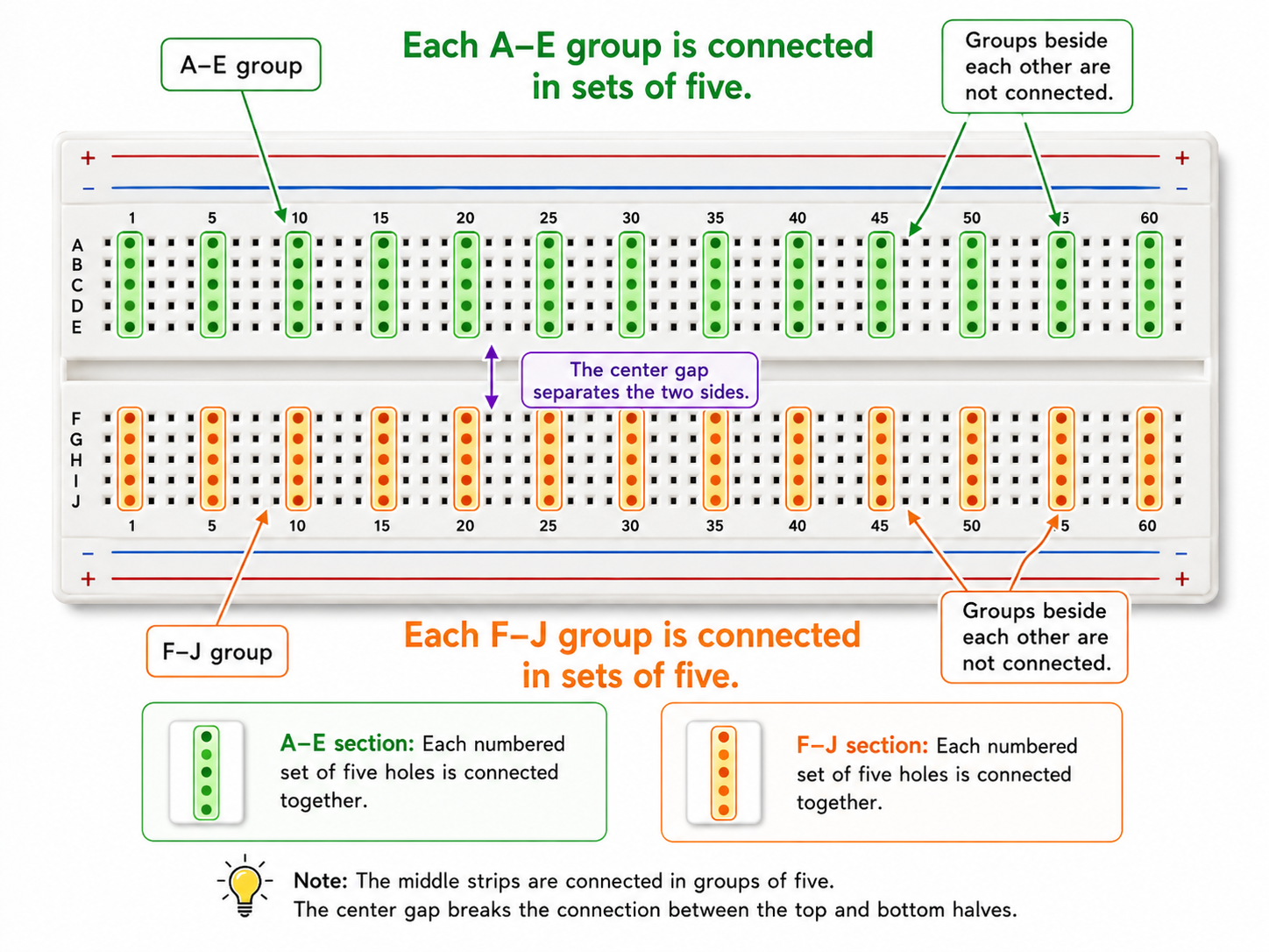
The middle section is where most components are placed. This is also the part that causes the most confusion for new users.
Each numbered position contains two separate groups of five connected holes.
For example:
A10, B10, C10, D10, and E10 are connected together
F10, G10, H10, I10, and J10 are connected together
Those two groups are not connected to one another because the center gap separates them.
The next numbered position is also separate. A10 is not connected to A11, even though the holes are beside each other.
It helps to think of each five-hole group as a small electrical meeting point. Any component leads or wires placed in that group are electrically joined.
For example, suppose the end of a resistor is placed in A10. A jumper wire placed in C10 would connect to that resistor because both holes belong to the same five-hole group.
A jumper placed in C11 would not connect to it.
A Common Source of Confusion
The printed letters and numbers make the layout look like a spreadsheet, but the internal connections do not run across the whole lettered row.
On the breadboard shown in the images, the connected groups run through A–E at one number, and separately through F–J at that same number.
Always follow the highlighted connection groups rather than assuming that nearby holes are connected.
What Is the Center Gap For?
The channel running through the middle of the breadboard separates the upper and lower terminal strips.
This gap is especially useful for integrated circuits, often called ICs or chips. A chip can sit across the gap so the pins on one side connect to the upper terminal groups and the pins on the other side connect to the lower groups.
The gap is also useful for simple components such as LEDs. Placing an LED across the gap ensures that its two leads are not accidentally connected together by the breadboard.
Building a Simple LED Circuit
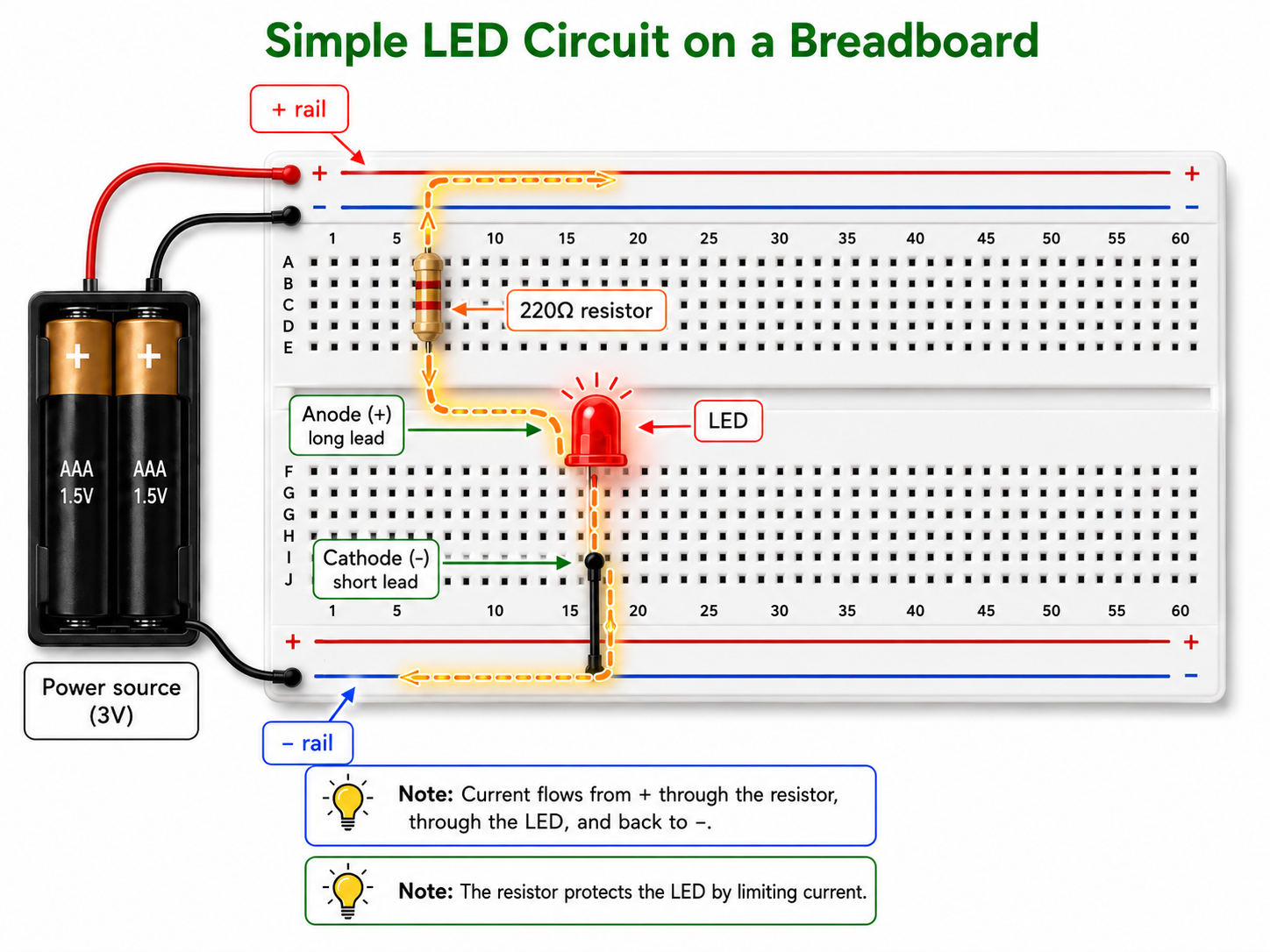
For this example, you will need:
A breadboard
One red LED
One 220-ohm resistor
A 3-volt battery pack
Jumper wires
A resistor between 220 and 330 ohms will normally work well for a basic red LED powered by approximately 3 volts.
Understanding the LED Leads
An LED has two leads:
The anode is the positive lead
The cathode is the negative lead
On a new LED, the anode is usually the longer lead. The cathode is usually shorter, and the LED body often has a flat edge on the cathode side.
The LED must face the correct direction. Current needs to enter through the anode and leave through the cathode.
Step 1: Connect the Power Source
Connect the red wire from the battery pack to the red positive rail.
Connect the black wire from the battery pack to the blue negative rail.
Do not turn on or connect the battery while you are still moving components around. Build the circuit first, check the connections, and then apply power.
Step 2: Add the Resistor
Place one end of the 220-ohm resistor into the positive power rail.
Place the other end into one of the five-hole groups in the upper terminal-strip section.
The resistor limits the amount of current flowing through the LED. Without it, too much current may pass through the LED and damage it.
Step 3: Add the LED
Place the LED across the center gap.
Put the anode, or long lead, into the same upper five-hole group as the resistor’s free end. Because those holes are connected internally, electricity can travel from the resistor into the LED.
Place the cathode, or short lead, into the lower section on the opposite side of the center gap.
The center gap keeps the two LED leads electrically separate. Current can only travel between them by passing through the LED itself.
Step 4: Connect the LED to the Negative Rail
Place one end of a black jumper wire into the same lower five-hole group as the LED’s cathode.
Place the other end of that jumper into the blue negative rail.
The complete path is now:
Battery positive → positive rail → resistor → LED → jumper wire → negative rail → battery negative
Once you have checked those connections, connect or switch on the battery pack. The LED should light.
If the LED Does Not Turn On
Start with the simple checks.
Make sure the LED is facing the correct direction. Reversing the LED is one of the most common beginner mistakes.
Check that the resistor and LED anode are actually in the same five-hole group. Being close together is not enough; they must be in holes that are internally connected.
Check that the cathode and black jumper share the same lower five-hole group.
Make sure the battery wires are connected to the correct rails, and confirm that the battery is installed properly.
Also inspect the power rails for a break in the middle. A wire connected to one half of a divided rail will not power components connected to the other half unless the two sections are joined with a jumper.
A Few Good Breadboard Habits
Disconnect power before changing the circuit. Low-voltage beginner projects are generally forgiving, but moving wires while power is connected can still cause short circuits or damage components.
Use red jumper wires for positive connections and black or blue wires for negative connections whenever possible. The colours do not change how electricity behaves, but consistent colour choices make circuits much easier to inspect.
Keep component leads reasonably short and avoid crossing too many wires over one another. A neat circuit is easier to understand and much easier to troubleshoot.
Most importantly, do not judge a connection by appearance alone. Two leads may be beside each other and still be electrically separate. Follow the breadboard’s hidden connection pattern.
The Main Idea to Remember
A breadboard is a reusable set of hidden electrical connections.
The long rails distribute power. The middle holes connect in small groups of five. The center gap separates the two main sections.
Once you understand those three ideas, a breadboard stops looking like a confusing grid of holes. It becomes a simple tool for joining components, testing ideas, and learning how a circuit works before making anything permanent.